
Views: 0 Author: Site Editor Publish Time: 2026-11-11 Origin: Site


In industrial environments handling flammable gases, vapors, or combustible dust, standard instrumentation wiring poses an unacceptable ignition risk. Relying solely on heavy explosion-proof enclosures is often costly, highly inflexible, and incredibly maintenance-heavy. You need a smarter approach to plant safety. Intrinsic safety (IS) offers a reliable preventative alternative. It ensures the instrumentation system simply lacks the electrical or thermal energy required to ignite a surrounding hazard. It maintains this protection even under multiple catastrophic fault conditions.
At the heart of this elegant protection method is the Intrinsic Safety Barrier. This guide breaks down how these barriers govern energy loops across your facility. We will explore the vital architectural differences between passive Zener designs and active isolated alternatives. Finally, you will learn the critical entity parameters required for compliance-driven procurement and flawless field implementation.
An intrinsic safety barrier restricts voltage and current under both normal and fault conditions, preventing thermal or electrical sparks in hazardous areas (Zone 0/1/2 or Class I, Div 1/2).
The primary architectural choice is between a passive Zener barrier (requires a dedicated high-integrity ground) and an Isolated Safety Barrier (galvanically isolated, eliminating strict grounding requirements).
Procurement requires matching barrier entity parameters ($V_{oc}, I_{sc}, P_o$) with field device limits ($V_{max}, I_{max}, P_i$) and accounting for cable capacitance and inductance.
Installing a barrier does not automatically make a system safe; comprehensive loop calculation and adherence to ATEX/IECEx/NEC standards are mandatory.
Process engineers face a strict compliance bottleneck when designing instrument loops for hazardous areas. Preventing industrial explosions requires removing at least one element of the classic ignition triangle: fuel, oxygen, or an ignition source. In chemical plants, refineries, or grain silos, removing the fuel or oxygen is rarely possible. The surrounding atmosphere inherently contains these elements. Therefore, removing the ignition source remains your only viable safeguard.
Intrinsic safety does not just protect the loop during normal daily operations. Engineers design these systems for worst-case scenarios. They strictly limit energy even if field wires short-circuit, internal components fail, or massive overvoltage occurs from the control room side. The barrier absorbs and dissipates this excess energy before it can travel down the wire and create a spark.
You can measure a successful implementation through several criteria. First, the system secures mandatory ATEX, IECEx, or NEC compliance. Second, it reduces the overall weight and footprint of control panels by eliminating bulky explosion-proof cast-iron housings. Finally, it allows for "live maintenance." Technicians can safely calibrate or replace sensors in the field without shutting down facility power, drastically improving operational uptime.
To understand energy clamping, you must look inside the barrier. A traditional safety circuit relies on a specific triad of electronic components. They work together to neutralize incoming electrical surges.
Zener Diodes: These components act as voltage clamps. If the voltage from the control room exceeds a safe threshold, the diodes instantly conduct the excess voltage and divert it safely to ground.
Resistors: These components limit the electrical current flowing into the hazardous area. Even if a dead short occurs in the field wiring, the resistor ensures the current never reaches a level capable of generating a thermal spark.
Fuses: These provide secondary, fail-safe protection. If a massive overvoltage destroys the Zener diode, the fuse immediately breaks the circuit, permanently isolating the field wiring from the power surge.
Physical placement defines the safety architecture. You must install the barrier in the safe, non-hazardous area. It resides inside a standard control cabinet. From this safe location, it acts as a strict gatekeeper for any signal wires passing into the classified hazardous zone. No unprotected wire may cross this boundary.
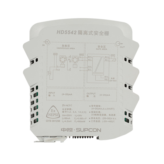
Engineers must choose between two primary technologies when designing an intrinsically safe loop. Your choice heavily impacts installation complexity, long-term maintenance, and signal reliability.
Zener barriers represent the older, traditional approach to intrinsic safety. They are entirely passive devices, meaning they require no external power supply to operate.
Their primary advantage is a lower upfront component cost. They also feature a smaller physical footprint and highly simplified internal circuitry. However, they carry a massive installation burden. A Zener barrier requires a highly regulated, dedicated intrinsically safe earth ground. This ground must maintain a resistance of less than one ohm. Maintaining this pristine ground in a massive steel facility is incredibly difficult. Furthermore, slight differences in ground potential can create ground loops, causing severe analog signal interference.
Modern facilities increasingly rely on active technologies. An Intrinsic Safety Isolator utilizes internal transformers or opto-isolators to achieve complete galvanic isolation between the safe area and the hazardous area.
This design completely eliminates the need for a dedicated intrinsically safe earth ground. It drastically reduces installation complexity. Furthermore, it inherently protects sensitive instrument signals against ground-loop noise. While an Isolated Safety Barrier requires external power and carries a higher initial unit cost, the installation savings usually offset the purchase price.
For modern facility upgrades or complex installations where guaranteeing a perfect earth ground is technically prohibitive, the isolated active design serves as the standard, lower-risk choice.
Table 1: Architectural Comparison of Safety Barriers
Feature | Zener Barrier (Passive) | Isolated Safety Barrier (Active) |
|---|---|---|
Galvanic Isolation | No | Yes |
Grounding Requirement | Strict IS earth ground (< 1 ohm) | No dedicated IS ground required |
External Power | Not required | Required (typically 24V DC) |
Ground Loop Risk | High | Eliminated |
Initial Component Cost | Lower | Higher |
Specifying a barrier requires rigorous mathematical validation. You cannot simply select a reputable brand and assume it protects your specific sensor. You must follow a strict evaluation framework known as the entity concept.
Matching Entity Parameters: The barrier's maximum output limits must never exceed the field device's maximum input limits. You must verify three distinct parameters. First, the barrier's Open Circuit Voltage (Voc) must be less than or equal to the sensor's Maximum Voltage (Vmax). Second, the Short Circuit Current (Isc) must be less than or equal to the sensor's Maximum Current (Imax). Finally, the Maximum Power (Po) must be less than or equal to the sensor's Maximum Power input (Pi).
Calculating Cable Allowances: The wiring itself acts as an energy storage device. Long cable runs store electrical energy. Buyers must calculate whether the total cable capacitance (Ca) and inductance (La) fit within the barrier's allowable safety limits. If the cable stores too much energy, a spark could still occur despite the barrier.
Evaluating Channel Density: Panel space in control rooms is highly valuable. Evaluate the physical form factor. Look for high-density DIN-rail mountability and multi-channel configurations. Dual-channel barriers can protect two separate sensor loops while occupying the space of a single unit.
Consider the HD5500 Safety Barrier as a benchmark example of modern specification. When reviewing such models, buyers must check specific certification ratings. You must verify SIL (Safety Integrity Level) ratings and ensure the ATEX zoning compatibility matches your specific site requirements.
Many procurement teams fall into a dangerous cognitive trap known as the "Component vs. System" fallacy. Buying a certified barrier does not automatically yield a certified, safe system. The intrinsic safety rating applies to the entire interconnected loop. You must mathematically validate the sensor, the cable, and the barrier together. Engineers document this validation in a mandatory file called the Descriptive System Document (DSD).
Installation pitfalls frequently destroy compliance. The most common mistakes occur during physical wiring.
Improper Grounding: This remains the leading cause of Zener barrier failure. If the dedicated ground wire corrodes or loosens, the barrier loses its ability to dump excess voltage, rendering the hazardous area completely unprotected.
Wire Separation Violations: Standards require strict physical segregation between intrinsically safe wiring and non-IS wiring. Installers must usually maintain a 50mm distance in cable trays and panels. Mixing these wires invites electromagnetic interference and accidental cross-wiring, which can inject lethal energy into the safe loop.
Device Substitution Risk: Maintenance teams sometimes swap a broken field sensor or a damaged cable for a "similar" one. If they fail to recalculate the entity parameters for the new parts, they instantly invalidate the safety rating. A sensor that looks identical might have higher internal capacitance, pushing the loop out of compliance.
Intrinsic safety barriers serve as the non-negotiable gatekeepers of hazardous area instrumentation. They reliably transform standard, high-energy control signals into low-energy, compliance-ready loops. By understanding their internal mechanisms, you can protect your facility from catastrophic ignition events.
When shortlisting devices, base your selection on grounding feasibility. If maintaining a perfect earth ground is impossible, default to isolated barriers. Always rigorously calculate your entity parameters, demand strict ATEX or IECEx certifications, and optimize for panel space efficiency.
As a next step, advise your engineering team to audit your current hazardous area loop calculations. Verify your Descriptive System Documents are up to date. Always consult a certified intrinsic safety systems engineer before specifying new barriers for upcoming facility expansions.
A: Explosion-proof methodology accepts that a spark will occur. It relies on heavy, robust mechanical enclosures to contain the resulting internal explosion, preventing it from igniting the outside atmosphere. Intrinsic safety takes a preventative approach. It limits the electrical and thermal energy in the circuit so a spark never possesses enough energy to cause an explosion in the first place.
A: No. Unlike traditional passive Zener barriers, isolated safety barriers utilize active galvanic isolation through internal transformers or opto-isolators. This advanced design completely removes the strict regulatory requirement for a dedicated, high-integrity intrinsically safe earth ground.
A: No. You must mathematically validate the components together. The barrier's maximum output parameters (voltage, current, and power) must not exceed the sensor's maximum input limits. Furthermore, you must account for the electrical energy stored in the connecting cable. This calculation framework is known as the entity concept.
A: Installing a barrier backward removes all protection. It will fail to clamp voltage or limit current traveling from the safe area control equipment into the hazardous area. This immediately invalidates your facility's safety compliance and creates a critical, unprotected explosion risk in the field.


