
Views: 0 Author: Site Editor Publish Time: 2026-11-08 Origin: Site


Modern industrial facilities demand absolute precision to run efficiently. Process control relies heavily on the precise manipulation of fluid dynamics. However, standard analog positioners often struggle in these demanding environments. They frequently fall victim to mechanical wear, stiction, and debilitating hysteresis. Recent technological shifts offer a much better approach. The transition from traditional mechanical linkages to microprocessor-based control changes the game. It shifts valve positioning from a reactive mechanical task to a proactive, data-driven process.
Plant managers and instrumentation engineers face difficult choices when evaluating system upgrades. You need a clear understanding of how these advanced devices translate control signals into physical actuation. You must also properly evaluate the right model for your specific process environments. Mastering this knowledge remains critical for your operation. It directly helps you maximize product yield and minimize unplanned downtime across your facility.
Intelligent positioners use closed-loop feedback and microprocessors to continuously compare the DCS control signal with actual valve stem position, instantly correcting deviations.
Advanced PID algorithms within smart positioners compensate for inherent mechanical flaws like friction and hysteresis, significantly improving overall control accuracy.
Upgrading from a traditional **pneumatic valve positioner** to a digital model unlocks predictive maintenance diagnostics, reducing unplanned outages.
Selecting the right unit requires balancing control precision with compliance ratings (e.g., an **explosion-proof valve positioner** for hazardous areas) and seamless DCS integration.
Standard positioners typically suffer from operational blind spots. The control room sends a signal to move a valve. Operators assume the physical valve responds exactly as commanded. Unfortunately, older mechanical units cannot verify the exact physical valve response. This lack of verification leads to process variability. It creates inefficiencies you cannot easily trace. Digital control fundamentally solves this business problem by ensuring precise tracking.
The solution relies heavily on advanced signal processing. An intelligent unit receives a standard 4-20mA analog signal. It often receives superimposed digital data via HART or Fieldbus protocols. It processes this hybrid signal digitally. Traditional units rely on a cumbersome mechanical flapper-nozzle system. Smart units eliminate these fragile mechanical linkages. The internal microprocessor analyzes the incoming setpoint immediately. It then calculates the exact pneumatic output required.
Current-to-pressure (I/P) conversion acts as the physical bridge in this process. Smart units utilize low-power piezoelectric valves or specialized servo valves. These components convert the digital command into targeted pneumatic output. They direct instrument air precisely into the actuator chamber. Piezoelectric valves respond in milliseconds. They consume very little electrical power. This makes them ideal for intricate process environments.
Continuous feedback forms the core of this closed-loop system. The positioner reads the actual valve stem travel continuously. Many modern units use a non-contact Hall effect sensor instead of mechanical arms. This sensor reads magnetic field changes as the valve stem moves. It feeds this exact position data back to the microprocessor. The system compares the actual position against the control setpoint. It closes the loop in milliseconds to correct any deviations.
Mechanical degradation poses a constant threat to process stability. Traditional units rely heavily on springs, levers, and physical linkages. These components degrade over time due to vibration and environmental exposure. A conventional Pneumatic Valve Positioner requires frequent manual recalibration. In contrast, digital units offer incredible operational stability. Microprocessors do not stretch, wear out, or corrode. They maintain their calibration digitally, ensuring long-term repeatability.
Air consumption represents a major operational expense for many plants. Traditional flapper-nozzle designs constantly bleed instrument air. They waste expensive compressed air even when the valve remains stationary. Intelligent positioners operate differently. They only consume instrument air when actively moving the valve. Their steady-state bleed rate drops to near zero. This efficiency drives measurable utility cost reductions across large facilities.
Maintenance strategies also shift dramatically with digital upgrades. Plants can finally move from preventive maintenance to predictive maintenance. Digital units log critical operational data continuously. They track total stroke counts and monitor friction changes. They record step-response times during normal operation. Technicians receive automatic alerts if a valve becomes sluggish. This data warns you long before a catastrophic failure occurs.
You can identify failing packing or actuator leaks early. Maintenance teams can order spare parts proactively. They schedule repairs during planned turnarounds instead of fighting emergency shutdowns. This predictive capability transforms how maintenance departments operate. It eliminates unnecessary teardowns of perfectly healthy valves.
Engineers frequently debate the true source of control accuracy. Some argue the mechanical valve body dictates ultimate precision. Others claim the positioner acts as the true brain. The reality sits somewhere in the middle. A positioner cannot fix a mechanically broken valve. A destroyed seat or severely bent stem requires physical replacement. However, advanced electronics can compensate for many inherent mechanical flaws.
Friction and stiction create massive headaches for process control. Stiction causes a valve to stick in place. The control system increases pressure to move it. The valve suddenly breaks free and overshoots the target. An Intelligent Valve Positioner solves this using proprietary PID algorithms. It applies aggressive pressure pulses to overcome packing friction. It rapidly tapers the pressure as the valve moves. This prevents the valve from overshooting the setpoint.
Linearization offers another massive advantage for process engineers. Many control valves exhibit non-linear flow characteristics naturally. A standard butterfly valve does not open linearly compared to flow rate. Microprocessors easily solve this mechanical limitation. They apply custom characterization curves directly to the control loop. You can program the device to make a non-linear valve behave perfectly linearly.
This digital characterization achieves much tighter process control tolerances. It allows you to use more cost-effective valve bodies in complex applications. The software compensates for the hardware's natural flow curve. Your Distributed Control System (DCS) sees a perfectly linear response. This simplifies loop tuning and stabilizes the entire process.
Selecting the right equipment requires a practical features-to-outcomes framework. Buyers often get lost in dense specification sheets. You must focus on what specs actually matter in the field. Every feature should directly solve a specific operational pain point.
Auto-calibration stands out as a mandatory feature. Traditional commissioning takes hours of manual tweaking. Modern digital units offer one-button auto-tuning. The device strokes the valve automatically. It measures friction, travel limits, and actuator volume. It sets its own PID parameters in minutes. This reduces commissioning time from hours to mere minutes.
Communication protocols dictate how well the unit integrates. You must verify compatibility with your existing host systems. HART 7 remains the most common standard for legacy upgrades. Foundation Fieldbus and Profibus PA offer robust digital integration for newer architectures. Choose a protocol your existing DCS can handle natively.
Diagnostic capabilities vary wildly between different manufacturers. You need to distinguish between basic and advanced diagnostics. Basic diagnostics typically require offline tests. You must bypass the valve to run stroke tests. Advanced diagnostics offer in-service friction analysis. They analyze valve health while the process remains running.
Diagnostic Tier Comparison
Diagnostic Level | Operational Mode | Key Features | Best Use Case |
|---|---|---|---|
Basic Diagnostics | Offline | Auto-calibration, step response tests, total stroke counts. | Standard utility loops, water lines, non-critical processes. |
Advanced Diagnostics | Online (In-Service) | Friction analysis, pneumatic leak detection, continuous supply pressure monitoring. | Critical chemical reactors, high-pressure steam, difficult access areas. |
We must offer a skeptical note regarding specifications. Warn your procurement team against over-specifying. A highly advanced diagnostic suite sounds impressive on paper. However, it only provides value if you use it. Your plant’s DCS and maintenance team must be equipped to parse the data. If no one monitors the software, advanced diagnostics waste capital budget.
Deploying electronic instruments in hazardous areas requires strict risk assessment. Chemical plants, oil refineries, and mining facilities handle volatile substances. Standard electronics pose severe ignition risks in these environments. A single stray spark can cause catastrophic damage. You must select equipment specifically designed for these harsh realities.
Engineers typically choose between two main protection methods. They use either explosion-proof or intrinsically safe designs. You must clearly understand the difference. An Explosion-Proof Valve Positioner utilizes a heavy, cast-metal enclosure. It allows internal explosions to occur. The robust enclosure cools escaping gases so they cannot ignite the outside atmosphere. This method works well when you have standard power levels.
Intrinsically safe (IS) models take the opposite approach. They use low-energy circuitry. The device simply cannot generate enough thermal or electrical energy to cause a spark. Even under fault conditions, it remains completely safe. This requires specialized safety barriers in the control room to limit power.
Procurement teams must rigorously verify industry-standard certifications. You should look for ATEX and IECEx ratings for global compliance. FM and CSA approvals dominate the North American market. If you operate safety instrumented systems (SIS), check the SIL ratings. A SIL 2 or SIL 3 certified device ensures high reliability for critical emergency shutdown valves.
Adopting digital valve control introduces a few practical implementation risks. Improper installation ruins even the best technology. Using incorrect or flimsy mounting kits causes severe sensor hysteresis. The positioner thinks the valve moves, but only the bracket flexes. Furthermore, dirty instrument air fouls internal pneumatics quickly. Digital controls cannot save you from wet, oily air clogging the tiny piezoelectric valves.
Smart shortlisting logic saves tremendous time and money. Advise your team to standardize plant inventory as much as possible. Standardizing reduces spare parts inventory. It significantly lowers training overhead for your technicians. Look for modular designs. Prioritize units offering broad actuator compatibility across both rotary and linear valves.
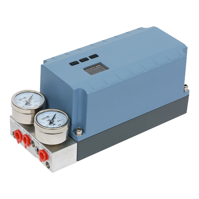
Establishing an evaluation baseline simplifies the selection process. The CVP2000 Valve Positioner serves as an excellent example of this baseline. It satisfies several critical criteria effortlessly. It provides robust vibration resistance for high-stress piping. It delivers precise PID control to eliminate overshoot. It offers simple retrofitting capabilities for older actuators. The straightforward commissioning process keeps project timelines on track.
We recommend a calculated next-step action for facility engineers. Do not attempt a plant-wide rollout immediately. Audit your worst-performing control loops first. Identify the valves causing the most process variability. Request a trial installation of a high-tier unit on these specific loops. Prove the return on investment through stable data before expanding the upgrade program.
Upgrading your control architecture yields immediate and measurable benefits. An intelligent valve positioner acts as much more than just a pneumatic accessory. It serves as the absolute "brain" of the control valve assembly. It directly dictates your overall process accuracy and mechanical reliability.
Take action by evaluating your most troublesome control loops today. Audit your compressed air quality to prepare for digital upgrades. Standardize your procurement requirements around seamless DCS integration and necessary hazardous area certifications.
By demanding transparent diagnostic data, facilities transform their maintenance strategies. Rigorous compliance and proven anti-friction algorithms ensure long-term stability. You can objectively justify the higher initial CapEx of these smart units. They pay for themselves quickly through reduced maintenance labor and highly optimized process yields.
A: Electro-pneumatic (I/P) positioners use analog components to convert current to pressure. They rely on mechanical parts that degrade over time. Intelligent positioners use a microprocessor, digital algorithms, and sensors for precise, auto-calibrating feedback. They eliminate mechanical linkages, offering predictive diagnostics and superior stiction compensation.
A: Yes. While they are digitally advanced, the pneumatic actuation components (like piezo valves) are highly sensitive to moisture, oil, and particulates. Contaminated air will clog internal ports and cause premature failure. Your air quality must meet strict ISA/ANSI standards for reliable operation.
A: Yes, provided the actuator is functioning properly and the correct mounting brackets (e.g., NAMUR standard) are used. Retrofitting is a highly common strategy to digitize legacy infrastructure without replacing the entire expensive valve body assembly.
A: Explosion-proof enclosures are typically chosen when the existing plant wiring cannot support intrinsically safe power limitations. They are also preferred in environments where heavy-duty physical protection of the electronics is necessary due to extreme external wear or potential impact damage.


