
Views: 0 Author: Site Editor Publish Time: 2026-08-14 Origin: Site


Selecting the wrong process instrumentation creates hidden bottlenecks across your facility. You often experience severe media clogging. Unscheduled downtime quickly follows these errors. Standard threaded connections simply fail in demanding environments. Harsh media rapidly builds up inside small connection ports. This buildup makes flush or extended flange connections absolutely critical for ongoing plant safety. They maintain measurement reliability over years of continuous operation.
This article provides a verified, engineering-focused framework. We help you evaluate and specify the ideal instrumentation. You will learn how to select the right flange type pressure transmitter for complex industrial applications. We outline precise sizing dimensions. We clarify material compatibilities for aggressive fluids. You will discover practical ways to avoid installation mistakes. Ultimately, this framework empowers your engineering team to maximize operational uptime.
Flange connections are non-negotiable for highly viscous, crystallizing, or particulate-heavy media where standard threaded ports clog.
Proper selection requires aligning ASME/ANSI flange sizes and pressure classes with maximum process conditions, not just nominal operating ranges.
Integrating a diaphragm seal pressure transmitter is essential for aggressive chemicals and high-temperature scenarios.
Total cost of ownership depends heavily on matching wetted part materials (e.g., Hastelloy, Monel, Tantalum) to the specific corrosive profile of the process media.
Engineers face severe operational risks when applying standard threaded connections in harsh environments. Narrow threaded ports naturally create flow dead legs. Process media stagnates inside these tight cavities. This stagnation causes false readings over time. Eventually, it poses severe leak hazards. Operators struggle to clear blocked ports safely. A well-engineered flange pressure transmitter eliminates these hidden dangers entirely. Flange mounts expose the sensing element directly to the main flow. They completely remove narrow entry paths.
Viscous fluids resist flow. Syrups, heavy oils, and polymers behave sluggishly inside pipeworks. They easily plug small measurement ports. High viscosity pressure measurement requires flush-mounted flange diaphragms. The sensor sits perfectly flat against the vessel interior. Thick fluid passes smoothly over the sensing element. This intelligent design prevents blockages. You receive continuous readings without dismantling the unit for manual scraping.
Certain chemicals solidify when temperatures drop. Standard cavities trap this susceptible fluid. The trapped fluid then crystallizes and ruins the delicate sensor. You need a dedicated crystallizing medium transmitter design. Flange configurations position the diaphragm directly in the active, heated flow. Continuous fluid movement prevents media solidification at the sensor interface. You receive highly accurate readings without constant maintenance purging.
Food processing and pharmaceutical plants require strict hygiene. Threaded ports hide dangerous bacteria. Flange alternatives offer seamless, crevice-free integration. They fully support Clean-in-Place (CIP) and Steam-in-Place (SIP) protocols. Operators wash systems thoroughly without removing the instruments. This capability ensures regulatory compliance. It also slashes turnaround times between production batches.
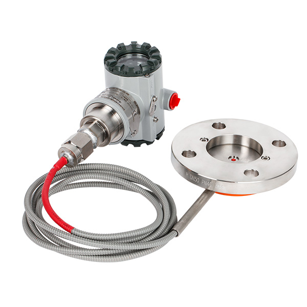
Proper specification demands strict adherence to international mechanical standards. You cannot guess flange dimensions. You must match recognized codes like ASME B16.5 or EN 1092-1. This alignment ensures a safe mechanical fit across your facility.
Pipes and vessels feature specific mating flanges. You must read and specify nominal sizes correctly. Common dimensions include 2-inch or 3-inch nominal pipe sizes (NPS). Next, you select the appropriate pressure rating. Standards group these into classes. Higher classes use thicker steel. They feature larger bolt patterns. They safely contain immense internal forces.
ASME Flange Class | Equivalent PN (Approximate) | Typical Application Use Cases |
|---|---|---|
Class 150 | PN 20 | Low-pressure storage tanks, municipal water systems |
Class 300 | PN 50 | General chemical processing, moderate steam lines |
Class 600 | PN 110 | High-pressure oil refining, heavy power generation |
You must choose between flush and extended designs based on specific vessel geometry. Mistakes here lead to poor readings or mechanical damage.
Flush flanges: Use these for standard vessel mounting. The diaphragm aligns perfectly flush against the inner wall of uninsulated pipes. They work best on single-wall tanks.
Extended flanges: Use these when piercing through tank insulation. Thick vessel walls leave standard sensors recessed deeply. An extended body pushes the diaphragm forward. It typically extends 2, 4, or 6 inches. It sits flush right against the actual internal media.
Buyers often focus strictly on nominal operating ranges. This singular focus causes premature sensor failure. You must always evaluate realistic pressure spikes. Large pumps create sudden mechanical surges. Rapid valve closures cause intense water hammer. Ensure your selected flange class safely contains these worst-case scenario pressures. Review the maximum overpressure limit stated by the manufacturer. It must exceed your highest possible system surge.
Standard applications rely on 316L stainless steel wetted parts. However, aggressive chemicals dissolve 316L rapidly. Integrating a robust diaphragm seal pressure transmitter isolates fragile electronics from hostile liquids. You must specify exotic wetted materials for harsh chemical engineering applications. Hastelloy C-276 provides exceptional resistance to strong acids. Monel works flawlessly for hydrofluoric applications. Tantalum handles extremely corrosive chloride environments. PTFE coatings prevent sticky substances from adhering to the metal. Match your selected metal strictly against the fluid's specific chemical profile.
Extreme process heat destroys microprocessors. Direct mounting fails almost immediately under these conditions. Reliable high temperature liquid level monitoring requires excellent thermal isolation. We achieve this using capillary systems and localized cooling towers. A capillary tube physically separates the hot process from the vulnerable electronics. It relies on an internal fill-fluid to transmit process pressure mechanically.
Fill-fluid selection directly impacts performance. Silicone oil handles standard ranges smoothly. High-temperature inert fluids resist boiling at extreme heat. However, denser fluids slow down the instrument's response time. You must balance thermal endurance limits against required measurement speed.
Pre-assembled seal systems require rigorous quality control. Never assemble seals and transmitters blindly on site. Always request factory leak tests before shipment. Demand calibration certificates for the complete assembly. This documentation guarantees the internal fill-fluid contains no trapped air bubbles. Trapped air compresses under pressure. It ruins the transmitter's accuracy permanently.
The best instrument fails if technicians install it improperly. Physical constraints often dictate horizontal or vertical mounting orientations. Capillary lines add measurable head pressure. The raw weight of the internal fill-fluid pushes against the sensor. This gravity effect directly shifts your zero-point calibration. You must perform a careful zero-trim after final mechanical installation. Always account for the specific gravity of the fill-fluid during this step.
Gasket selection causes many common field failures. Improper gasket sizing overlaps the diaphragm physically. This minor error warps the thin protective foil. It ruins measurement accuracy entirely. Uneven torqueing creates identical hazards. Technicians must apply torque in a strict star pattern using a calibrated wrench. Failure to follow this sequence causes fugitive emissions. It also introduces severe mechanical stress on the measuring cell.
Maintenance requires safe access. We highly recommend specifying flush rings. You install these between the flange and the process connection. Flush rings feature small radial ports. They allow technicians to inject cleaning fluids locally. You can vent trapped hazardous gases safely. Operators perform accurate field calibration without removing the heavy transmitter from the main vessel.
Navigating supplier catalogs feels overwhelming. Follow this exact sequence to narrow down your technical choices efficiently.
Step 1: Process Media Audit. You must determine if the fluid demands a specialized interface. Check for high viscosity. Look for crystallizing tendencies. Note any corrosive chemical elements. Record extreme operating temperatures.
Step 2: Vessel/Pipe Interface. Identify the exact existing mating connections. Note the nominal size accurately. Check the specific facing type (Raised Face, Flat Face, or Ring Type Joint). Verify the required international mechanical standard.
Step 3: Environmental and Safety Constraints. Evaluate the ambient conditions surrounding the physical installation. Check the external temperature range. Confirm if the zone requires hazardous area certifications like ATEX or IECEx. Assess structural vibration levels near large pumps.
Step 4: Operational Lifecycle Evaluation. Avoid short-term thinking. Balance the upfront material selection against daily operational reality. Cheap alloys fail early. They cause hidden maintenance burdens. They trigger unexpected plant shutdowns. Specifying robust materials prevents premature sensor failure. It guarantees long-term operational stability.
Specifying the right instrumentation requires balancing mechanical fit, chemical compatibility, and thermal isolation perfectly. You must analyze fluid characteristics carefully. Match wetted materials precisely to avoid corrosion and buildup.
Avoid over-specifying. Excessive exotic materials waste critical engineering budgets unnecessarily.
Avoid under-specifying. Weak materials risk catastrophic safety failures and unexpected downtime.
Always verify physical constraints. Ensure extended lengths match tank insulation exactly.
Perform field zero-trimming. Account for hydrostatic head pressure in vertical capillary installations.
Take action today. Gather your Piping and Instrumentation Diagrams (P&ID). Collect your detailed process data sheets. Share these technical documents directly with application engineers. They will provide final validation for your instrument selection.
A: A direct mount establishes a physical connection right at the process vessel. It provides a shorter response time. However, it features a severely limited temperature range. Capillary lines separate the sensor physically from the process. They provide excellent thermal isolation for hot media. The internal fluid does cause a slightly delayed response time.
A: No, you face strict mechanical limitations. Manufacturers calibrate diaphragm sizes at the factory for specific fluid volumes. Changing physical flange adapters alters the required mechanical forces. Modifying these components directly impacts accuracy. It also voids factory warranties immediately.
A: You must follow strict handling guidelines. Keep the protective plastic covers on until the absolute last moment. Never touch the fragile metal foil with bare hands or sharp tools. Strictly follow the manufacturer's bolting torque sequence to prevent accidental warping.


