
Views: 0 Author: Site Editor Publish Time: 2026-07-22 Origin: Site


Selecting the right differential pressure transmitter is rarely a plug-and-play decision. Mismatches lead to false readings, process inefficiencies, and premature sensor failure. When you deploy a sensor, you expect precise and reliable data. However, application realities often compromise standard devices. In critical process control loops, engineers must balance baseline technical specifications against severe environmental conditions. Corrosive media, extreme static pressure, and sudden temperature shifts threaten measurement integrity daily. You cannot rely on datasheet accuracy numbers alone. This guide provides an evidence-based framework for evaluating, shortlisting, and specifying these critical instruments. We base our approach on exact application demands and operational risk factors. You will learn how to match sensor types to distinct field challenges. By following this methodology, you ensure stable measurements and avoid unexpected instrument failures in your facility.
Application dictates design: Flow, level, and filter monitoring require fundamentally different installation practices and sensor configurations.
Material compatibility (wetted parts) and overpressure limits are often more critical to long-term ROI than baseline accuracy specs.
Advanced sensor technologies, such as the monosilicon transmitter, provide superior stability in environments with fluctuating static pressures and temperatures.
Final selection must account for environmental compliance (e.g., ATEX, SIL ratings) and seamless integration with existing control systems (HART, Foundation Fieldbus).
Before reviewing manufacturer catalogs, you must define what successful measurement looks like for your specific process. Standard accuracy requirements only tell a fraction of the story. You must evaluate long-term stability and total probable error (TPE) under real-world conditions. Ambient temperature shifts and line pressure fluctuations impact the final reading. True precision accounts for these variables.
You also need to assess the cost of failure. Calculate the business impact of sensor drift and recalibration downtime. In hazardous loops, a delayed response triggers safety incidents. Unexpected drift forces operators to shut down processes for maintenance. You must align your instrument choices with operational risk limits. A highly stable sensor minimizes these unscheduled interventions.
System architecture alignment happens before evaluating vendor specifications. Map out your requirements for local displays, remote diagnostics, and required response times. Some loops demand instantaneous updates, while others benefit from dampened signals. By defining your industrial pressure measurement architecture early, you eliminate unsuitable models immediately.
You cannot use identical specification logic for every installation. A reliable DP pressure transmitter adapts to the unique physics of the task. Flow, level, and equipment health monitoring present distinct engineering challenges.
Flow measurement introduces dynamic fluid mechanics into your instrument selection. You must integrate the sensor seamlessly with primary elements. Orifice plates, Pitot tubes, and Venturi meters create the differential pressure you need to measure. Each primary element generates specific pressure drop profiles. You must match the transmitter range to these profiles accurately.
This application typically requires square root extraction. The relationship between differential pressure and flow rate is non-linear. The flow measurement transmitter must calculate the square root locally or send raw data to a control system. You must also manage low-flow cutoff parameters. At the bottom of the flow range, signal noise mimics actual flow. Setting proper cutoff thresholds prevents false readings and maintains process stability.
Monitoring liquid levels in closed vessels requires calculating hydrostatic pressure differentials. You must consider fluid density and precise vessel geometry. Changes in fluid temperature alter density, which shifts your reading. You must account for these density variations during your initial calibration phase.
Installation methods dictate long-term success. You must choose between wet leg and dry leg installations. A dry leg works for gases that do not condense. A wet leg is necessary for vapors that condense in the impulse piping. For viscous or high-temperature media, standard piping fails. In these cases, you must specify a tank level transmitter equipped with remote seal systems. Remote seals isolate the delicate sensor diaphragm from destructive process media.
Equipment health monitoring prioritizes protection over absolute precision. You use the transmitter to monitor pressure drops across filters or pumps. First, you establish baseline pressure drops for clean, optimal states. Then, you set strict alarm thresholds for potential clogs or dangerous pump cavitation.
In these scenarios, prioritize rapid response times and robust overpressure protection. When a pump block occurs, pressure spikes instantly. An ultra-high precision sensor shatters under this stress if it lacks proper overpressure limits. You need a rugged device capable of surviving sudden hydraulic shocks.
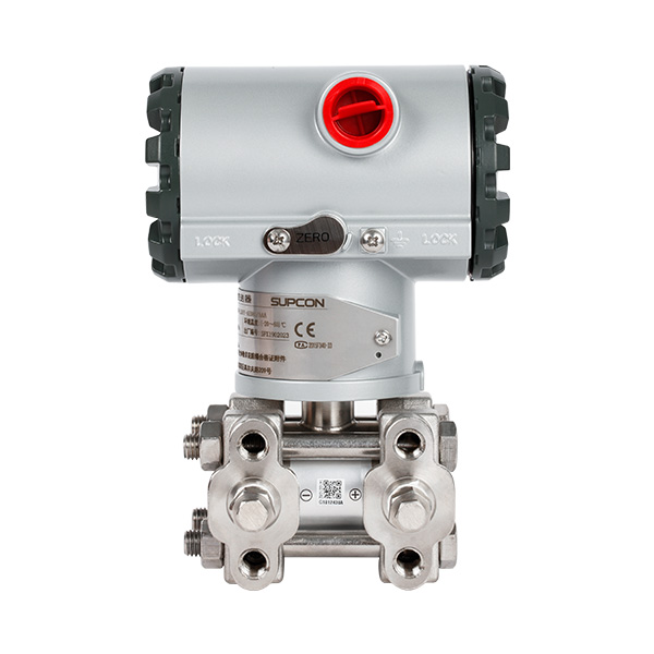
Once you define the application, you must evaluate the internal mechanics of the instrument. The sensor technology, ranging capabilities, and material science determine the survival rate of your device.
Manufacturers utilize various sensor architectures to detect pressure changes. Traditional capacitive sensors rely on fluid-filled cavities and moving diaphragms. They offer reliable service but often struggle under severe temperature fluctuations. Advanced piezoresistive designs use solid-state technology to detect strain. They react faster and provide improved baseline stability.
For applications demanding high accuracy and fast recovery, evaluate the monosilicon transmitter. This architecture uses a single crystal silicon measuring element. It excels in environments requiring rapid recovery from extreme overpressure events. Monosilicon technology virtually eliminates hysteresis and minimizes static pressure errors. It delivers exceptional stability even when process conditions fluctuate wildly.
The turndown ratio defines the operational flexibility of your instrument. A high ratio allows you to adjust the calibrated range without replacing the hardware.
Match ratio to process variations: Select a turndown ratio (e.g., 100:1) that accommodates expected flow or level changes.
Consolidate inventory: A flexible range allows you to stock fewer discrete models in your warehouse.
Avoid over-specification: Do not buy excessive turndown capabilities simply because they exist.
Manage signal degradation: Operating a sensor at the extreme bottom of its turndown range amplifies static noise and reduces accuracy.
You must find the optimal balance between inventory consolidation and measurement resolution. Always calibrate the device as close to your normal operating pressure as possible.
Wetted parts physically touch your process media. Selecting the wrong material causes rapid corrosion, leakage, and catastrophic failure. You must evaluate diaphragm materials aggressively against media corrosiveness. Common options include 316L Stainless Steel, Hastelloy, Monel, and Tantalum. You must also evaluate hydrogen permeation risks. In hydrogen-rich environments, atomic hydrogen penetrates standard diaphragms, altering the internal fill fluid.
Fill fluids transfer pressure from the external diaphragm to the internal sensor. You must select appropriate fluids based on operating temperature extremes and process sanitary requirements. Silicone oil handles standard industrial temperature ranges well. Inert oils are mandatory for oxygen service to prevent combustion. FDA-approved oils are required for food and pharmaceutical applications.
Wetted Material Compatibility Matrix | ||
Diaphragm Material | Primary Application Strengths | Common Limitations / Risks |
|---|---|---|
316L Stainless Steel | Standard water, steam, and mild chemicals. | Corrodes quickly in high-chloride environments. |
Hastelloy C-276 | Severe corrosives, sulfuric acids, and seawater. | Susceptible to hydrogen permeation at high temps. |
Monel | Hydrofluoric acid and alkaline processing. | Not suitable for nitric acid or ammonia. |
Tantalum | Highly aggressive acids (hydrochloric, nitric). | Brittle under extreme mechanical stress. |
Even the most advanced sensor fails if installed poorly. You must manage physical footprint constraints, environmental extremes, and future maintenance accessibility.
Impulse piping connects the process pipe to the transmitter. These lines are notorious for leaks and blockages. You must minimize leak points by utilizing integrated manifolds. A 3-valve manifold allows you to isolate and equalize the sensor for flow measurement. A 5-valve manifold adds venting capabilities for gas applications.
You must address the physical footprint and weight constraints on existing process lines. Bulky installations cause excessive strain on thin-walled pipes. Close-coupled manifold designs eliminate long runs of impulse tubing. They reduce the total weight of the assembly and improve response times by minimizing the fluid volume between the pipe and the sensor.
Ambient conditions outside the pipe disrupt measurement just as much as process conditions inside. You must mitigate the effects of ambient temperature fluctuations. In freezing climates, impulse lines easily freeze and burst. You must protect them through heat tracing or specialized environmental enclosures. Heat tracing maintains fluid viscosity, but you must monitor it to prevent overheating the sensor.
You must also account for high-vibration environments. Compressors and large pumps generate vibrations that loosen electrical connections and cause mechanical fatigue. Utilize robust housing options, such as dual-compartment designs. These designs separate the sensitive electronics from the terminal block, preventing moisture ingress and resisting mechanical shock.
Maintenance teams operate under strict time constraints. You must assess the calibration burden before purchasing. Evaluate the frequency of zero-trimming required by the specific sensor architecture. Highly stable sensors require zero-trimming once every five years. Cheaper sensors demand quarterly adjustments.
Evaluate the availability of predictive diagnostics. Modern transmitters detect anomalies before they cause a shutdown. They monitor electrical noise to identify plugged impulse lines. They alert technicians when the process standard deviation shifts unexpectedly. These built-in diagnostics allow your maintenance team to transition from reactive troubleshooting to proactive, scheduled maintenance.
The final phase involves integrating the physical device into your digital and safety infrastructure. You must verify communication protocols, safety ratings, and vendor reliability.
Communication Protocol Comparison Chart | ||
Protocol Type | Architecture Fit | Diagnostic Capabilities |
|---|---|---|
4-20mA Analog | Legacy PLC systems, simple loops. | None (Requires physical inspection). |
HART | Hybrid systems needing remote access. | High (Superimposes digital data on analog). |
Foundation Fieldbus | Complex, fully digital plant networks. | Very High (Multi-variable and advanced alerts). |
Modbus RS485 | SCADA systems, long-distance transmission. | Moderate (Good for basic remote polling). |
Your existing control infrastructure dictates the required output signal. You must choose between standard 4-20mA analog, HART, Modbus RS485, or Profibus. For simple, isolated loops, a standard analog signal suffices. However, if you require remote diagnostics and multi-variable data, you must specify a digital protocol.
HART remains the industry standard for upgrading legacy systems. It layers digital information over existing analog wiring. Foundation Fieldbus and Profibus suit new, fully digital architectures. Match the protocol strictly to your existing PLC or DCS capabilities to avoid costly integration delays.
Industrial environments frequently contain flammable gases and combustible dust. You must ensure regulatory compliance to protect your facility.
Explosion-proof ratings: Verify ATEX, IECEx, FM, or CSA certifications for heavy enclosures that contain internal blasts.
Intrinsically safe ratings: Ensure the device operates on energy levels too low to ignite hazardous atmospheres.
Functional safety: Confirm Safety Integrity Level (SIL 2/3) data for integration into Safety Instrumented Systems (SIS).
Sanitary standards: Check for 3-A or EHEDG certifications if operating in food and beverage environments.
Never install a device lacking the proper regional and application-specific certifications. The legal and operational risks are simply too high.
The best technical specification fails if the vendor cannot support it. You must prioritize vendors offering transparent MTBF (Mean Time Between Failures) data. Reliable manufacturers publish their testing methodologies openly.
Evaluate the availability of localized technical support. When a critical loop goes down, you cannot wait for overseas support teams to respond. Require proven traceability for all wetted materials. A trustworthy vendor provides material test reports (MTRs) to verify the exact metallurgical composition of your instrument.
Sourcing a differential pressure transmitter is a rigorous balancing act. You must align process application requirements, complex material science, and stringent safety compliance. Relying on baseline accuracy alone leads to rapid failure in harsh industrial settings. You must evaluate static pressure limits, impulse piping constraints, and digital diagnostic capabilities.
Your next action is immediate documentation. Engineers should compile their specific process conditions—including min/max pressure, media type, temperature range, and protocol—into a standardized specification sheet. Do this before requesting vendor technical proposals or CAD models. A comprehensive spec sheet ensures you receive instruments perfectly sized for your specific operational challenges.
A: A standard gauge measures pressure at a single point relative to atmospheric pressure. A differential transmitter measures the exact drop between two distinct points in a system. Furthermore, it outputs a continuous electronic signal (like 4-20mA or HART) for automated control, whereas a gauge typically offers only a local visual readout.
A: You should specify remote seals when dealing with highly corrosive, extremely viscous, or crystallizing media. They are also essential for extreme temperature applications that would melt or freeze the internal sensor components. The seals keep destructive fluids away from the sensitive transmitter body.
A: High static line pressures physically distort the sensor housing and diaphragm. This distortion causes a zero-shift error, making the differential reading inaccurate. You must evaluate a transmitter’s maximum static pressure limits and its internal compensation algorithms to ensure stable readings under high line pressures.
A: Calibration intervals depend heavily on industry regulations, environmental harshness, and sensor architecture. While older models require bi-annual checks, advanced piezoresistive or monosilicon sensors often maintain stability for up to five years. Always align calibration schedules with your facility's safety and compliance mandates.


