
Views: 0 Author: Site Editor Publish Time: 2026-09-14 Origin: Site


Industrial environments demand absolute precision. Fluctuating temperatures and high pressures constantly threaten process accuracy. Heavy foam and varying fluid densities further complicate operations. You need reliable tools to prevent critical failures. This is the primary challenge of modern liquid level detection. To solve it, engineers turn to the guided wave radar level meter. We define this device as a highly specialized contact level meter. It utilizes Time Domain Reflectometry (TDR) to calculate distance, level, and volume accurately.
Standard sensors often lose their signal in harsh conditions. However, this robust technology maintains consistent accuracy. It bypasses common environmental interference entirely. This guide unpacks its core operational mechanics. We will examine critical structural limitations in detail. You will also see direct comparisons against other transmitter types. We explore the specific use cases where this technology shines. These practical insights directly aid your procurement and engineering evaluation. You will learn exactly how to match the right probe to your process medium.
Immunity to process conditions: Guided wave radar (GWR) performance is largely unaffected by variations in pressure, temperature, vapor, or fluid density.
Direct surface contact: Unlike free-space radar, GWR uses a physical probe to guide microwaves, making it ideal for low-dielectric fluids and confined spaces.
Implementation reality: While highly accurate, GWR requires careful probe selection and installation due to physical risks like probe fouling and pull-down forces.
Strategic fit: It is the optimal choice for complex tank level measurement where ultrasonic or non-contact solutions experience signal loss.
How does it actually work? We must look closely at the TDR mechanism. The transmitter electronics generate low-energy microwave pulses. It sends these pulses down a rigid or flexible probe. This physical probe acts as an efficient waveguide. The pulse travels downward at the speed of light. It stays entirely focused along the metallic path.
Eventually, the pulse hits the liquid surface. This medium possesses a different dielectric constant than the vapor space above it. The sudden change in the dielectric constant causes a measurable reaction. The microwave pulse reflects immediately upon hitting this boundary. The energy bounces back up the probe directly to the sensor head.
The onboard microprocessor measures the exact time delay. We call this critical measurement the time-of-flight calculation. It tracks the exact duration between signal emission and its return. Because microwave speed remains perfectly constant, this calculation is foolproof. It determines the exact distance from the sensor to the product surface. You then subtract this precise distance from the total known tank height. This simple math yields the actual product volume.
Why does this matter for practical engineering decisions? The signal remains tightly constrained to the waveguide. Energy loss is virtually zero. The microwave pulse does not scatter into the open tank space. You get highly reliable readings even in intensely turbulent environments. Foaming tanks do not disrupt the guided microwave energy. The reflection remains sharp and distinguishable.
You might wonder how this technology compares to other solutions. We examine the stark differences below to clarify your options.
Non-contact versions broadcast a wide, invisible signal beam. This beam spreads out as it travels downward toward the liquid. Because of this spread, they are highly susceptible to false echoes. Agitators, heating coils, and internal ladders often reflect the beam prematurely. They also struggle heavily with very low-dielectric liquids.
Conversely, guided wave devices keep the signal concentrated solely on the physical probe. You eliminate beam spread entirely. This structural advantage makes them perfect for tall, narrow tanks. They perform exceptionally well inside small bypass chambers. You get strong, clear echoes even from extremely poor reflectors.
Ultrasonic devices rely purely on mechanical sound waves. This creates severe environmental vulnerabilities. Sound requires stable air molecules to travel accurately. Ultrasonic sensors fail under extreme temperature gradients. Heavy vapors, dense dust, and vacuum conditions destroy their acoustic signals.
Guided wave equipment operates via electromagnetic waves. They do not need air molecules to propagate. This fundamental difference renders them fully immune to acoustic interference. Thick vapor layers do not slow the electromagnetic pulse. They function flawlessly even in total vacuum environments. They easily outclass acoustic methods in demanding industrial setups.
Comparison of Level Measurement Technologies | |||
Feature / Condition | Guided Wave Radar | Non-Contact Radar | Ultrasonic Transmitter |
|---|---|---|---|
Signal Type | Electromagnetic (Guided) | Electromagnetic (Free-space) | Acoustic (Sound waves) |
Vacuum Performance | Excellent | Excellent | Fails completely |
Foam Handling | Very Good | Poor to Fair | Poor (Absorbs sound) |
Obstruction Tolerance | Excellent (Ignores them) | Poor (Creates false echoes) | Poor |
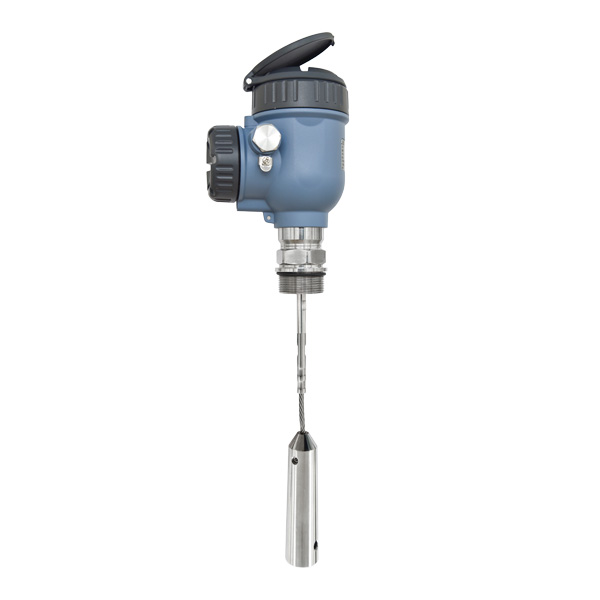
Engineers must evaluate several factors before installation. Proper tank level measurement requires strict attention to process variables.
Selecting the correct physical probe dictates your overall success. Different media require different shapes.
Coaxial Probes: These work best for low dielectric fluids. Clean hydrocarbons are a perfect example. The outer metallic tube prevents external signal loss. It traps the microwave energy tightly. However, they are highly prone to clogging in viscous applications.
Twin Cable or Rod: These offer a good middle ground. They provide stronger signals than single rods. They also resist clogging much better than coaxial types.
Single Cable or Rod: We suggest these for heavier, sticky liquids. They also handle bulk solid silos very well. They resist bridging and thick material buildup. They are slightly more susceptible to signal dispersion, though.
Every medium possesses a specific dielectric constant. This value dictates the signal reflection strength. Standard units require a baseline DK requirement. Typically, a DK of 1.4 or higher works reliably. You can also execute interface measurement. Detecting oil floating over water requires distinct DK differences. The upper layer must have a low DK. The lower layer must have a high DK. The microwave pulse partially reflects off the top surface. The remaining energy continues downward to reflect off the bottom surface.
You must review critical specifications during procurement. Look for strict industry safety certifications. SIL 2 and SIL 3 certifications ensure regulatory compliance. Verify pressure ratings if your process exceeds normal limits. Some units handle up to 400 bar easily. Confirm high-temperature tolerance limits for heated reactors.
Consider industrial-grade models during your evaluation process. For example, evaluating the SL901 level meter provides a solid baseline. Look for rapid response times. Ensure the unit offers specific flange integrations for your existing nozzles. Check if the device provides built-in dual-layer interface capabilities.
Even the best technology has hard limitations. You must acknowledge where a radar level transmitter fails if improperly applied. Improper installation creates massive engineering headaches.
Probe Fouling and Buildup: Viscous or crystallizing media pose severe operational risks. Sticky fluids can easily bridge the gap inside coaxial probes. They can evenly coat single suspension cables. This thick coating causes immediate false echoes. It shifts the dielectric reading along the probe. This ruins your accuracy entirely. You must implement regular cleaning schedules for heavy liquids.
Pull-Down Forces: Solid and bulk applications require extreme caution. The sheer weight of shifting material is immense. Granular media settles and pulls downward. It exerts massive tensile force on flexible cables. This risks snapping the probe mid-operation. Extreme pull-down forces can even collapse the physical tank roof. You must calculate these structural loads beforehand.
Blanking Zones (Dead Zones): Pay close attention to the measurement extremes. Upper and lower dead bands naturally exist. These blanking zones sit near the process connection and the very bottom tip. Measurements become highly unreliable in these specific zones. The electromagnetic signal transitions between mediums here. You must size your probe slightly longer than your minimum required measuring range.
Nozzle Clearance: Mounting nozzles demand strict best practices. Keep the nozzle neck as wide and short as possible. Prevent signal interference from sharp metallic burrs. Ensure the metallic probe does not touch the nozzle walls. Centering the probe stops erratic jumpy readings.
You need a clear and actionable decision framework. We break down the shortlisting logic below to simplify your engineering choices.
We recommend a guided wave solution under several specific parameters.
Choose it for low-dielectric liquids: It excels where non-contact radar loses signal strength.
Choose it for heavy steam or dense foam: The physical waveguide punches right through atmospheric interference.
Choose it for narrow bypass chambers: The lack of beam spread makes it the only viable radar option here.
Choose it for interface measurement: It reliably tracks liquid-liquid boundaries like oil and water.
However, you should absolutely avoid it in certain specialized scenarios.
Avoid it for highly corrosive media: Aggressive acids might attack and dissolve all available probe materials.
Avoid it for extremely sticky fluids: Heavy adhesives or thick resins will blind the physical sensor entirely.
Avoid it for strict sanitary requirements: Food and beverage applications often mandate strictly non-contact solutions to prevent bacterial contamination.
Matching the sensor to the exact process environment ensures longevity. A careful review of these constraints prevents costly implementation mistakes down the road.
Let us quickly review the core technical advantages. A guided wave radar level meter offers unmatched reliability for complex and harsh process conditions. It perfectly bridges the functional gap between traditional mechanical floats and complex free-space radar systems. The physical waveguide directly eliminates common atmospheric disruptions. It ignores pressure spikes, temperature gradients, and heavy foam.
Take specific action steps next. Review your specific tank dimensions thoroughly. Document your fluid dielectric constants accurately. Check your physical mounting availability and existing nozzle sizes. Compile these crucial engineering parameters first. Then, request comprehensive technical sizing from a qualified vendor. Proper preparation and upfront calculation guarantee your long-term operational success.
A: Yes, provided the upper fluid has a significantly lower dielectric constant than the lower fluid. A common example is oil floating over water. The initial microwave pulse reflects off the oil surface. The remaining energy continues down the probe. It then reflects off the denser water layer. This dual-reflection mechanism allows simultaneous total and interface tracking.
A: Flexible cable probes typically measure up to 30 to 60 meters. This translates roughly to 100 to 200 feet. However, the exact range depends heavily on the specific transmitter model. The dielectric constant of the medium also impacts the maximum reach. Low dielectric fluids weaken the signal faster, reducing the effective measuring distance.
A: No. Electromagnetic wave speed remains perfectly constant. Fluctuating pressure and temperature changes in the vapor space do not alter this speed. Because the fundamental time-of-flight math never changes, these devices generally do not require periodic wet calibration. They provide exceptional long-term stability with minimal maintenance intervention required by plant operators.
A: It handles agitation exceptionally well. The rigid probe design cuts directly through turbulent fluid dynamics. For extreme agitation, you should install it inside a bypass chamber or a stilling well. These structures physically isolate the probe from the violent movement. You receive perfectly stable readings despite heavy mixing inside the primary process vessel.


