
Views: 0 Author: Site Editor Publish Time: 2026-09-22 Origin: Site


Specifying a 26GHz radar level meter demands more than skimming basic technology overviews. You must actively match precise hardware configurations to your exact process media. In modern plants, decision-makers cannot afford guesswork. Misjudging the medium’s dielectric constant leads to costly false echoes. Ignoring surface agitation or vapor profiles causes sudden, catastrophic signal loss. These seemingly minor oversights eventually result in environmental compliance failures and severe process downtime. We designed this guide to solve these exact problems directly. You will explore a pragmatic, medium-first framework today. This proven approach helps you evaluate and shortlist the correct non contact radar level meter for highly specific industrial environments. We break down the necessary steps clearly. You will learn how to map your liquids, slurries, and dry bulk solids to the right antenna designs safely.
26GHz radar provides the optimal balance of beam penetration and cost-efficiency for most standard industrial level measurement applications, but requires precise antenna matching.
Liquid media evaluation must prioritize dielectric constants and surface conditions (foam, turbulence, vapor).
Solid media evaluation must account for angle of repose, dust generation, and low-reflective properties.
Shortlisting requires mapping the medium to specific antenna designs (e.g., horn vs. encapsulated) and accounting for tank internal structures.
Engineers often ask when exactly a 26GHz system represents the optimal solution. The answer lies deep in its versatile physical properties. We consider it the absolute industry workhorse for many practical reasons. It offers a highly functional moderate beam angle. It delivers strong microwave signal penetration through dense condensation. You can rely on its measuring range spanning 30 to 70 meters easily. These technical traits make it remarkably reliable for typical chemical and water processing facilities.
You must evaluate it rigorously against common alternative technologies. Ultrasonic sensors suffer greatly in fluctuating temperatures and pressures. A 26GHz device ignores these harsh atmospheric shifts entirely. What about higher frequencies? An 80GHz sensor handles extremely heavy foam and thick condensation slightly better. However, 26GHz provides more than enough performance for standard applications. It balances measurement reliability and lower hardware complexity effectively. This balance saves facility budgets without sacrificing safety.
You must establish clear success criteria for accurate solid liquid level sensing before purchase. First, determine your medium's minimum dielectric constant. The radar requires sufficient surface reflectivity to bounce the microwave signal back. Second, ensure a clear line of sight down the vessel. Internal obstacles block the radar beam quickly. Meeting these two baselines ensures steady, continuous operation across decades.
Best Practice: Always verify your medium's dielectric constant under actual operating temperatures. Heat can change reflective properties significantly.
Common Mistake: Installing standard units in highly pressurized vessels without checking the pressure rating of the antenna seal.
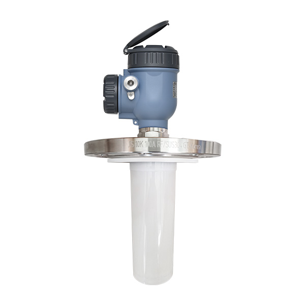
Different industrial liquids behave uniquely under high-frequency radar waves. You must adapt your hardware selection to these specific physical behaviors carefully.
Water and municipal wastewater facilities present their own distinct field challenges. You will face heavy morning condensation frequently. Minor surface turbulence occurs around pump cycles constantly. Outdoor environmental factors add immense unpredictability. Standard metallic horn antennas work perfectly here. Simple encapsulated drop antennas also perform exceptionally well. You should prioritize high IP ratings for outdoor basins. Focus heavily on securing maintenance-free operation to reduce long-term municipal labor costs.
Corrosive acids and aggressive base chemicals require extreme caution. Sensor degradation happens very quickly in harsh sulfuric environments. Hazardous area compliance strictly regulates your installation options. You should select PTFE or PFA encapsulated antennas immediately. These advanced materials prevent aggressive chemical corrosion entirely. You must also verify intrinsically safe electrical certifications. Look closely for Exia or Exd ratings before finalizing any hazardous area purchase.
Volatile hydrocarbon liquids and thick mining slurries introduce severe signal disruptions. Heavy chemical vapors fill the entire tank head-space above the product. Foaming and rolling boiling surfaces scatter radar signals randomly into the tank walls. You need high-gain antennas to punch through these disruptions successfully. Advanced signal processing algorithms become absolutely mandatory here. They filter out the chaotic false echoes generated by rolling liquid surfaces. Many engineers use stilling wells for highly turbulent tank radar level transmitter setups. A stilling well creates a perfectly calm liquid column for precise reading.
Best Practice: Use an integrated drip-off antenna design in high-condensation chemical tanks to prevent droplet formation.
Common Mistake: Ignoring the vapor phase dielectric constant in sealed hydrocarbon tanks, which slows the radar wave and causes reading errors.
Solids introduce entirely different physical variables compared to standard liquids. Airborne particles, steep material slopes, and uneven surfaces complicate the measurement process immensely.
Powders and heavy dust environments pose significant risks to continuous operation. Think of active cement silos or industrial flour bins. Thick airborne particles cause massive signal attenuation. Material buildup on the sensor lens blocks the microwave emission entirely over time. You must specify very large horn antennas. A larger horn maximizes the signal focus and punches through dense dust clouds effectively. We strongly recommend integrated air-purge systems. An air-purge connection blasts plant compressed air across the lens. This mechanical action keeps the antenna clean and guarantees continuous readings without manual climbing.
Granular chunks and bulk solids behave unpredictably as they fill a vessel. Grains and stone aggregates pile up very unevenly. They form a distinct, sloped angle of repose. These dry materials often possess incredibly low dielectric constants. This physical trait yields exceptionally weak return signals. You need specialized aiming flanges to solve the surface angle issue. Swivel mounts allow you to direct the radar beam precisely. You point it perfectly perpendicular to the material slope. This orientation maximizes the microwave signal reflection back to the receiver head. Always evaluate your minimum required measuring ranges carefully. Deep agricultural silos demand tighter beam angles to reach the very bottom cleanly.
Best Practice: Always map the empty silo structure during commissioning to suppress echoes from cross-beams.
Common Mistake: Mounting the radar in the direct filling stream, causing heavy abrasion and false maximum-level readings.
Antenna design dictates exactly how the microwave signal travels and focuses. You must match the physical shape strictly to your specific medium. Let's look closely at the three primary hardware configurations.
Horn antennas handle the absolute widest variety of complex industrial tasks. They are best for standard liquids, dry bulk solids, and deep long-range applications. Evaluation note: Physical size matters significantly here. Larger horns naturally yield much narrower beam angles. They produce much stronger, concentrated signals. This concentrated strength is critical for penetrating low-dielectric media successfully. You generally want the largest horn your existing tank nozzle can accommodate safely.
These specialized designs protect the internal metallic elements completely from the atmosphere. They are best for highly corrosive liquids. You will see them utilized heavily in hygienic food applications and heavy condensation environments. Evaluation note: Always verify chemical compatibility rigorously. You must ensure the chosen encapsulation material matches your specific process medium. PTFE resists most harsh chemicals brilliantly, but you should always double-check standard chemical resistance charts first.
Parabolic dish shapes concentrate the high-frequency radar wave intensely. They are best for extreme long-range solid measurement tasks. They handle dry materials exhibiting ultra-low dielectric constants perfectly. Evaluation note: This specific antenna requires significant mounting space above the tank. You typically reserve them for massive storage silos. They rarely fit into standard, tight process vessels safely.
Here is a detailed comparison chart summarizing the primary hardware configurations for your easy reference:
Antenna Type | Ideal Media Category | Key Operational Challenge Addressed | Crucial Evaluation Metric |
|---|---|---|---|
Standard Horn | Water, Oils, Bulk Solids | Signal scatter and extreme distance limits | Horn diameter vs. existing nozzle size |
Encapsulated (PTFE) | Acids, Caustics, Food Grade Liquids | Harsh corrosion and hygiene compliance | Material chemical compatibility |
Parabolic Dish | Dry Powders, Plastics, Cement | Ultra-low dielectric signal returns | Available roof mounting diameter |
Even the perfect radar sensor fails miserably if installed incorrectly. You must bridge the critical gap between engineering theory and actual field application smoothly.
First, assess your strict mounting and installation realities. You must measure nozzle height and internal diameter limitations accurately. The antenna edge must protrude past the nozzle bottom. If it sits inside a long nozzle, it causes immediate signal ringing. Ringing creates massive false echoes right at the top of your tank. Identify all internal tank structures beforehand. Agitators, heating coils, and internal ladders reflect microwaves powerfully. These metallic obstacles require careful empty-tank mapping. Modern digital transmitters use advanced false echo suppression to ignore these stationary objects entirely.
Next, practice evaluating glossy vendor specifications very critically. Do not accept optimal laboratory accuracy claims blindly. Know how to read accuracy specs realistically. Harsh process conditions like heavy vapor degrade ideal accuracy noticeably. You should benchmark against proven, field-tested industry models. Assessing a reliable device like the SL902 radar level meter helps establish baseline configuration standards. It shows exactly what features actually work in complex media.
Finally, execute structured next-step actions deliberately. Do not rush the final purchase order. Follow these specific steps to secure the right equipment:
Compile a comprehensive process data sheet immediately. List the exact medium, expected dielectric constant, and daily temperature ranges.
Document precise physical tank dimensions. Include exact nozzle sizes, locations, and internal obstacle coordinates.
Identify your worst-case atmospheric conditions. Note the highest possible pressure spikes and densest vapor states.
Request demonstration trial units for high-risk applications. Real-world testing proves long-term reliability better than brochures.
Ask for vendor-backed computational signal simulation. Many leading manufacturers can model exact signal propagation in your specific tank.
Successful facility automation depends entirely on physical measurement alignment. You must strictly marry the specific medium's physical properties to the correct 26GHz antenna and housing configuration. There is absolutely no universal sensor designed for every tank. Customizing the hardware ensures consistent data collection.
We advise process engineers to prioritize functional reliability under worst-case process conditions always. Do not size your vital equipment based on optimal, clean laboratory conditions. Plan specifically for the maximum airborne dust load. Account fully for the highest possible chemical foam generation. A sensor programmed to survive the worst day will perform flawlessly every other normal day.
Take direct action today to secure your operational process safety. Compile your raw technical requirements and seek expert validation quickly. We recommend you download our sizing questionnaire for industrial level measurement right now to organize your specifications. You can also consult an application engineer directly to verify your specific medium calculations and avoid costly misapplications.
A: Standard 26GHz devices typically require a minimum dielectric constant between 1.5 and 1.8. Materials falling below this range yield return signals too weak for reliable processing. If you must measure ultra-low dielectric media like dry plastics or liquefied gases, you should install a stilling well. The stilling well concentrates the microwave energy, artificially boosting the signal reflection back to the sensor.
A: It depends heavily on the foam's characteristics. Light, airy foam absorbs high-frequency microwave signals quickly. Dense, wet foam acts like a new liquid surface, reflecting the beam early. A 26GHz radar struggles with extremely thick, absorptive foam layers. In these heavy foam scenarios, you should specify lower-frequency radars or utilize physical bypass chambers to bypass the foam entirely.
A: You must specify a sensor with an integrated air purge connection. This mechanical feature allows you to pipe compressed air directly over the antenna lens. Periodic blasts of air keep the surface clear of airborne particles. Additionally, choosing smooth, encapsulated antenna designs helps minimize the available surface area where dust can physically accumulate over time.
A: Non contact radar sends free-space microwaves through the air to bounce off the medium. Contact radar, known as guided wave radar, sends pulses down a physical cable or rod immersed in the medium. Free-space 26GHz avoids media tangling and physical wear entirely. Guided wave radar ignores surface foam better but suffers greatly from sticky buildup on the probe over time.


